Science: Physics:
Hydraulic Resistance of Bodies in Water Flow
By Dr. Alexander B. Shandyba
Sumy State University, Ukraine
ABSTRACT:
The paper presents the calculation model for hydraulic resistance of bodies in
water flow. Experimental verification is made for the axially symmetric cases.
A satisfactory agreement is obtained to confirm the influence of the local
attack angle and current cross-sectional area of flow contraction.
1.
INTRODUCTION
The
conical contraction is the most widespread unit of many technical systems.� Also it is the noticeable sample of
hydrodynamic interaction between flow and streamlined bodies. In this
consideration we shall be limited by the developed turbulence regime that
allows us to examine the influence of the contraction geometry, pressure
distribution, energy losses and drag resistance.
2.
THEORY
It was
found that the loss of pressure in axially symmetric conical contraction (fig.
1) is connected with the excess pressure of viscous flow to ideal flow by the
following equation:
![]() ���������� (1)
���������� (1)
where ![]() �is loss of pressure,
�is loss of pressure, ![]() �is lesser cross-sectional area, r, R are radiuses of
lesser and greater cross sections, and f(r) is excess pressure of viscous flow
to ideal flow.
�is lesser cross-sectional area, r, R are radiuses of
lesser and greater cross sections, and f(r) is excess pressure of viscous flow
to ideal flow.
To
determine this function f(r) we suppose the whole flow in the contraction as
the complex of elementary streams where pressure and velocity are averaged on
time according to the Reynolds-Boussinesqe model [1,5].
Taking
into account the change of the flow structure in contraction, one must consider
the two characteristic sections of the flow: before and into contraction. The
character of the interaction of each stream with the conical surface depends on
its initial disposition in flow before contraction and the contraction
geometry. At this point of view the boundary streams seem to be most important.
Under the unseparated streamlining movement, these have quite defined ways like
the contraction formative lines [1,2].
Using
the impulse conservation equation the excess pressure can be found for the
boundary streams. Thus, if a liquid particle with mass equal ![]() �has the impulse
�has the impulse ![]() �in cross-section 1-1�
(where k0 is ratio of boundary stream velocity to average flow
velocity before contraction), then its impulse will be equal
�in cross-section 1-1�
(where k0 is ratio of boundary stream velocity to average flow
velocity before contraction), then its impulse will be equal ![]() �after interacting with the conical surface under
attack angle
�after interacting with the conical surface under
attack angle ![]() .
.
The
corresponding excess pressure in the connection point of conical contraction
will be defined from Bernoulli's equation:
![]() ���������� (2)
���������� (2)
where
excess pressure function� ![]() ���������������������� (3)��������������
���������������������� (3)��������������
The
experimental data confirm the presence and proportionality of the excess
pressure to ![]() �function [1,2,5]. It is important to note the
increasing of excess pressure along the boundary streams on any head
streamlining surface under contraction of flow. This takes place because there
is energy redistribution in contraction connected with increasing energy of the
boundary streams and accordingly decreasing energy of the inside streams. The
corresponding excess pressure occurs due to the change of impulses of the
inside streams. The value of pressure change may be found from the following
arguments.
�function [1,2,5]. It is important to note the
increasing of excess pressure along the boundary streams on any head
streamlining surface under contraction of flow. This takes place because there
is energy redistribution in contraction connected with increasing energy of the
boundary streams and accordingly decreasing energy of the inside streams. The
corresponding excess pressure occurs due to the change of impulses of the
inside streams. The value of pressure change may be found from the following
arguments.
First,
the excess pressure of real flow to ideal flow is the result of the interaction
between flow and the inside surface of contraction. It is connected with the
changes of velocities and, accordingly, liquid particles' impulses in the
streams. Moreover, only a part of impulse energy is consumed for increasing
potential energy of the boundary streams. This increasing conforms to ![]() �function.
�function.
�From the impulse conservation we can see that
interaction of the inside streams with the contraction surface will be
analogous with the boundary streams' interaction under their turning.� In other words, a ratio of excess potential
f and kinetic ![]() �energy is kept
constantly on all inside surfaces of the conical contraction,
�energy is kept
constantly on all inside surfaces of the conical contraction,
i.e., if��� ![]() �,�
�,� ![]() �=
�= ![]() ������������� �4 )
������������� �4 )
Generally
speaking, the distribution of the excess energy in the boundary streams depends
on the initial impulses distribution in flow and the local angles of
interaction with the contraction surface. The excess energy distribution can be
expressed as the sum:
![]() ������������������ (5)
������������������ (5)
Second,
the velocity of considering streams will increase in accordance with reduction
of cross-sections of the contraction as well as the excess pressure will
increase proportionally to the contraction degree function ![]() . It is very
essential that the summary increase of kinetic energy of the boundary streams
consists of the ideal and impulse components. The impulse component is
increased by energy reduction of the inside streams having the liquid particles
with rkV1 impulses,
where k function increases from k0 to kmax
for axis.
. It is very
essential that the summary increase of kinetic energy of the boundary streams
consists of the ideal and impulse components. The impulse component is
increased by energy reduction of the inside streams having the liquid particles
with rkV1 impulses,
where k function increases from k0 to kmax
for axis.
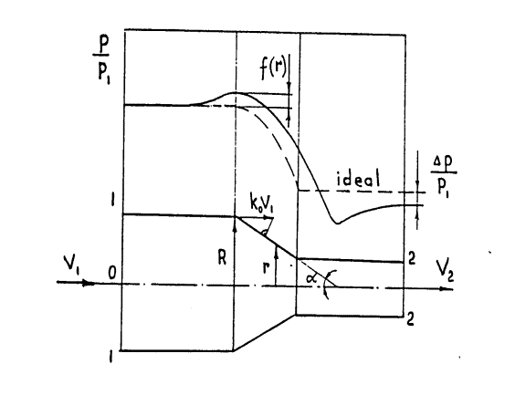
Figure 1.� Excess pressure of viscous flow to ideal
flow
At the
same time, the ideal component is increased by Bernoulli's equation and
correlated to R4 /r4 function in accordance with the continuous equation.
By the same reason, the summary increase of kinetic energy of the boundary
streams also is correlated to this contraction degree function [6,7].
Evidently,
the impulse kinetic component dj is
changed as the difference in analogous way:
![]() ������� (6)
������� (6)
Therefore,
from eq. (5) the excess pressure will depend on this function too:
![]() ������������������ (7)
������������������ (7)
As
integral, the excess pressure distribution on inside surface of contraction is:
![]() �������� (8)
�������� (8)
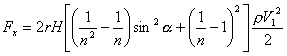
The
shape component of drag resistance force can be defined as:
 ������������� (9)
3.
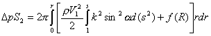
AXIALLY SYMMETRIC CASE
Flattening
the k function can be observed under a sufficiently large Reynolds number and
even profile of velocity before contraction. But these conditions are
characteristic rather for the external streamlining. In this case we shall
consider a cylindrical body with conical head situated in tube (fig.2).
Obviously,
we can note the peculiar ring contraction at the conical head. Then the
hydraulic losses coefficient of the whole body xx may be
presented as the sum:
![]() �������������� (10)
�������������� (10)
where xh xf xs are the hydraulic
loss coefficients of the ring contraction, cylindrical surface friction and
Borda's sudden expansion after stern.
Assuming![]() , k = 1 on the
analogy of (9) results in:
, k = 1 on the
analogy of (9) results in:
 ������������������������������ �(11)
or after integrating:
 ������������������ (12)
where �![]() �,�
�,� ![]()
For ![]() ��we have the widespread experimental Idelchik's
formula:
��we have the widespread experimental Idelchik's
formula:
![]() ������� (13)
������� (13)
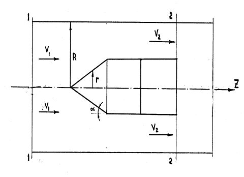
Figure 2. Ring contraction at the conical head
From
Borda's formula:
![]() ������� (14)
������� (14)
Then
the shape component of drag resistance force for a short cylinder with a
conical head disregarding of friction xf= 0 can be expressed as
:
![]() ������������� (15)
������������� (15)
Table 1
gives the comparison between calculated and experimental data of drag
resistance coefficient for different contraction degree and free flow.
Table 1. Influence of taper angle and ratio of
cross-sectional areas
on drag resistance coefficient (calculation/experiment)
|
n |
Taper angle of head |
|||
|
60o |
90o |
120o |
180o |
|
|
0.1 |
103.5/102 |
126/125 |
148.5/146 |
171/174 |
|
0.2 |
21/20 |
26/26 |
31/30 |
36/37 |
|
0.3 |
7.4/7.2 |
9.3/9.5 |
11.3/11.5 |
13.2/13.0 |
|
0.4 |
3.2/3.3 |
4.1/4.2 |
5.1/4.9 |
6.0/6.0 |
|
0.5 |
1.5/1.6 |
2.0/2.0 |
2.5/2.4 |
3.0/2.9 |
|
0.6 |
0.72/0.7 |
1.0/0.98 |
1.3/1.3 |
1.56/1.60 |
|
0.695 |
0.35/0.39 |
0.51/0.52 |
0.67/0.67 |
0.82/0.83 |
|
Free flow (exper.) |
0.38 |
0.52 |
0.66 |
0.82 |
4.
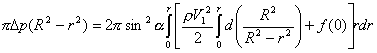
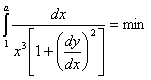
SYMMETRIC 2D CASE
It can
be shown that drag resistance of pier head in stream channel with sufficient
depth H on the analogy of (9) is:
 ����������� (16)
Assuming a=
const, k = 1, xf = 0 , we obtain the analogous of (15) expression:
![]() ��������� (17)
��������� (17)
or:
 ������� (18)
where 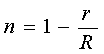 �.
�.
At the
same time, it is important to see that there is a possibility to reduce the
drag resistance by improving shape of pier head (fig.3). Engaging by the new
dimensionless coordinates:
![]() ������������ (19)
������������ (19)
we have the boundary conditions:
![]() ����������� (20)
����������� (20)
��������������������
and the ![]() �function as:
�function as:
 ������������ (21)
Thereby,
in the accepted coordinates system for k = const, the optimal shape of pier
head must provide the minimum of the integral:
 ���������������� (22)
In
other words, the Euler's differential equation must be executed:
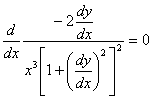 ���������������� (23)
But
this means that the differentiating expression is constant C. Involving the
positive
parameter ![]() ��we obtain the equations system:
��we obtain the equations system:
 ���������������� (24)
![]() �where
�where![]()
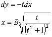
After
transformation:
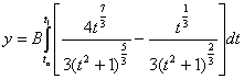 ����������� �(25)
Thus,
we have the parameter model for the convex curves family with reducing
curvature along flow. For the right solution one must employ the boundary
conditions (20).
5.
CONCLUDING REMARKS
The
results shown in the present paper concern mainly water flow but may be used
for the calculation of lifting force and Lilienthal polar of asymmetric bodies
in 2D/3D airflow. The main problem of the proposed approach is to identify the
contraction degree function correctly, defined only for inside problem of
hydroaerodynamics.
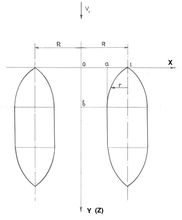
Figure 3. Improving shape of pier head
REFERENCES:
1. Daily J., Harleman D., 1971,
"Fluid Mechanics", Energy Book Comp. Moscow (transl. from English).
2. Gurevich M.I., 1979, "Theory of
jets in ideal fluids", Nauka Publish. Inc/, Moscow (in Russian).
3. Wieghardt T. "Uber
Antriebsverteilung des einfachen Rechteckflugel uber die Tiefe", ZAMM,
1939, Bd 19, H.5.
4. Relf E.F., Powell C.H."Tests on
smooth and stranded wires inclined to the wind direction", Rep. N 307,
ACA, 1916/17.
5. Shandyba A.B. "Hydraulic
Resistance of Conical Contraction", in "Collection of articles on Chemical
Machine-building", Kiev, 1992, pp. 89-94 (in Russian).
6. Shandyba A.B. "Pressure
distribution on head surface of axially symmetric bodies", - Proc. of the
"Research and Education - 98 Conference, April 8-9, Sumy, 12 pp., 1998.
7."Numerical Methods in Fluid
Dynamics". Ed: Wirz H.J., Smolderen J.J.-von Karman Institute for Fluid
Dynamics, Hemisphere Publ. Corp.
Dr. Alexander Shandyba is Assistant Professor of Safety Vital Activity
at Sumy State University and heads a research group at New Technology Institute.
He has
devised numerous
projects and is the author of 60 technical papers and inventions. Dr. Shandyba is also a Member of the publishing
board of the Mechanical Engineering Journal.
[ BWW Society Home Page ]
© 2002 The BWW Society/The Institute for the Advancement of Positive Global Solutions